01Overview
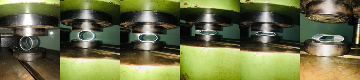
Thin-walled tubes are used as energy absorbers in vehicles, aircraft and structures. In the ring (lateral) compression test a tube lies on its side between two rigid flat plates and is squashed across its diameter. Seen along the load, it takes a saddle shape. The test is simple, and its load–deflection curve carries enough information to back out the material's yield stress, elastic modulus and strain hardening.
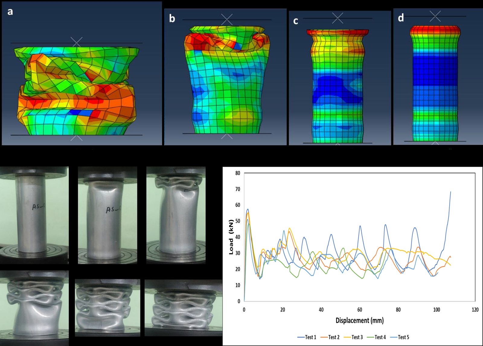
This was part of a wider study of aluminium tube deformation and impact energy absorption, with experiments, analytical models and finite-element models compared side by side.
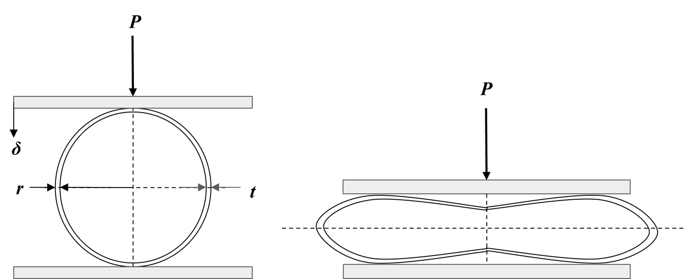
02Load–deflection response
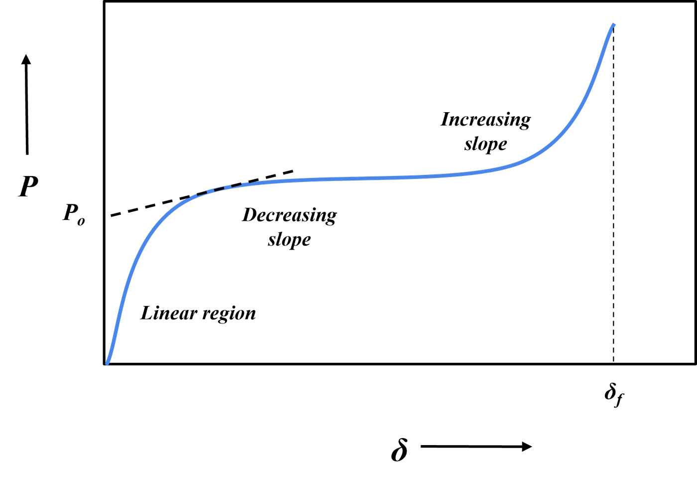
The curve has three phases:
- Elastic: load rises linearly and the tube springs back if unloaded.
- Yield: plastic hinges form and the load levels off at the collapse load .
- Hardening: the slope rises again as the material strain-hardens and the geometry stiffens.
03Experiment
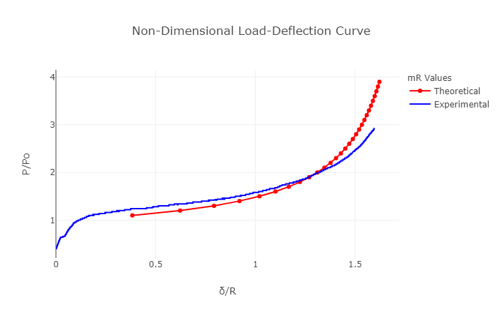
An aluminium 6063 tube, 50 mm long, 50 mm in diameter and 1.6 mm thick, was compressed at a constant 4 mm/min. The load–displacement record was taken together with photographs of each stage of the collapse. The collapse load, read where the tangents to the elastic and plastic parts meet, was 0.94 kN.
04Properties from the test
Yield stress from the limit load (with for short rings, , and for long tubes, ), and elastic modulus from the elastic load and deflection (DeRuntz and Hodge; in plane stress, in plane strain):
With kN, kN, mm, mm, mm and mm:
- Yield stress
- 183.6 MPa
- Young's modulus
- ≈ 68 GPa
- Hardening modulus
- 1.08 GPa
05Theory and fit
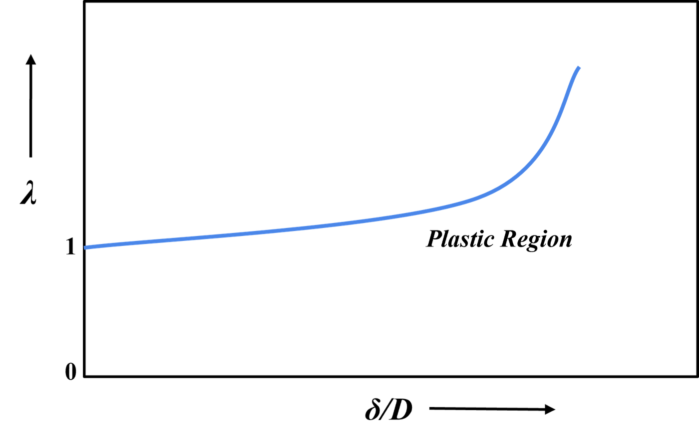
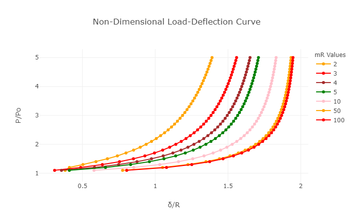
Reid and Reddy describe the hardening response with one non-dimensional parameter, which sets the shape of the load–deflection curve:
The test curve is made non-dimensional (load over collapse load, , against deflection over radius, ) and laid over the theoretical curves for a range of . The best fit was , which gives the average hardening modulus:
The code that draws the theoretical curves and fits them to a test record is on GitHub.
06References
- Reid, S. R., and Reddy, T. Y. (1978). Effect of strain hardening on the lateral compression of tubes between rigid plates. International Journal of Solids and Structures.
- Reddy, T. Y., and Reid, S. R. (1979). Lateral compression of tubes and tube-systems with side constraints. International Journal of Mechanical Sciences.
- Reddy, T. Y., and Reid, S. R. (1979). On obtaining material properties from the ring compression test. Nuclear Engineering and Design.