
Datum Pipe
Pipe stress analysis on the desktop: displacements, support loads, nozzle loads and code stresses, with an automatic isometric.
For Piping, stress, mechanical, process and plant engineers, consultants and students.
What Datum Pipe is
Datum Pipe works out how a piping system moves and what it pushes on when it heats up, carries its weight and holds its pressure. You type the piping as a table of elements, the way a stress engineer marks up an isometric, and it appears in 3D as you type: pipes at their true diameter, bends, tees, reducers, valves, flanges and supports.
Put on the supports, temperatures, pressures and equipment movements; the load cases are built for you. Analyze solves every case with Datum Pipe's own 3D pipe element solver, checks the stresses using the equations of the process piping code (ASME B31.3), and shows the results on the model, in tables of displacements, support loads and nozzle loads, on an automatic isometric drawing and in a printed stress report. Allowable stresses are your inputs, and Help › Verification solves benchmark problems with known answers in front of you.
- Step 1
Route the piping
Type each element's From node, To node and lengths in the table; pick the pipe, material, line conditions and component (bend, tee, reducer, valve, flange). It draws in 3D at once.
- Step 2
Support and load it
Add anchors, rests, guides, line stops, springs and nozzle points; set up to three operating temperatures and pressures, the hydrotest and equipment movements.
- Step 3
Check and report
Analyze, see the stress ratios on the model, read the support and nozzle loads, and print the stress report with the isometric and the equilibrium checks.
What it does
- A
An element table that draws the piping in 3D as you type: true diameters, insulation, bends, tees, reducers, valves, flanges and support symbols
- B
Pipe sizes ½" to 24" in every schedule, five piping materials with properties against temperature and their sources, and your own sizes and materials
- C
Anchors, one-way rests, guides, line stops and restraints with gaps and friction, skewed restraints, springs, constant-force supports and imposed equipment movements
- D
Load cases built for you: sustained, operating, expansion range and hydrotest
- E
Code stresses calculated using the equations of the process piping code: hoop stress and minimum wall (straight pipe, bends at their intrados, both ends of reducers), sustained stress and the displacement stress range, with PASS or FAIL at every point
- F
Support loads for the civil team and nozzle loads in the nozzle's own axes, checked against your allowables
- G
An automatic isometric drawing with dimensions, node numbers and result tags, and a printed stress report
- H
Help › Verification: benchmark problems with known answers solved in front of you, and an equilibrium check after every solve; Help › Sources: where every equation is published
Screens
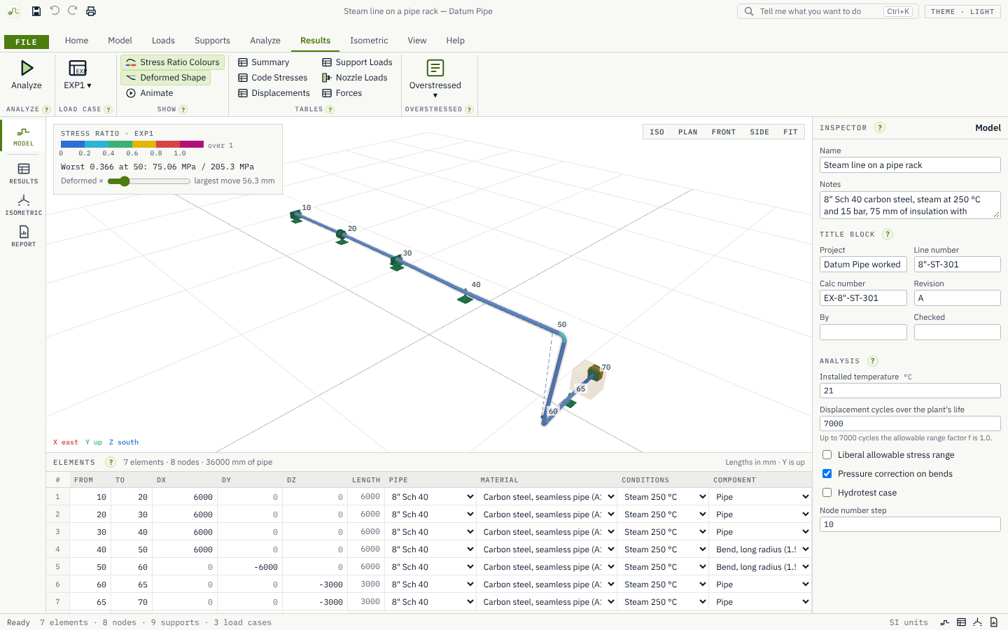
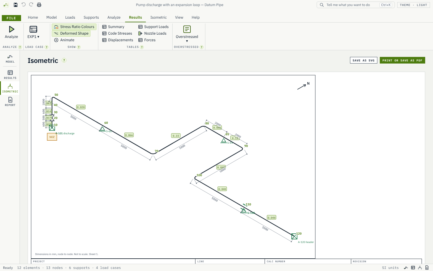
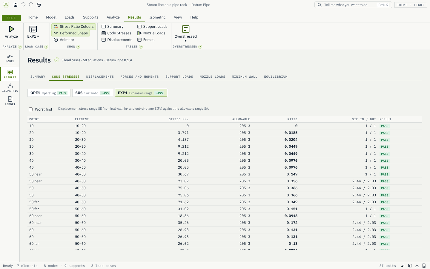
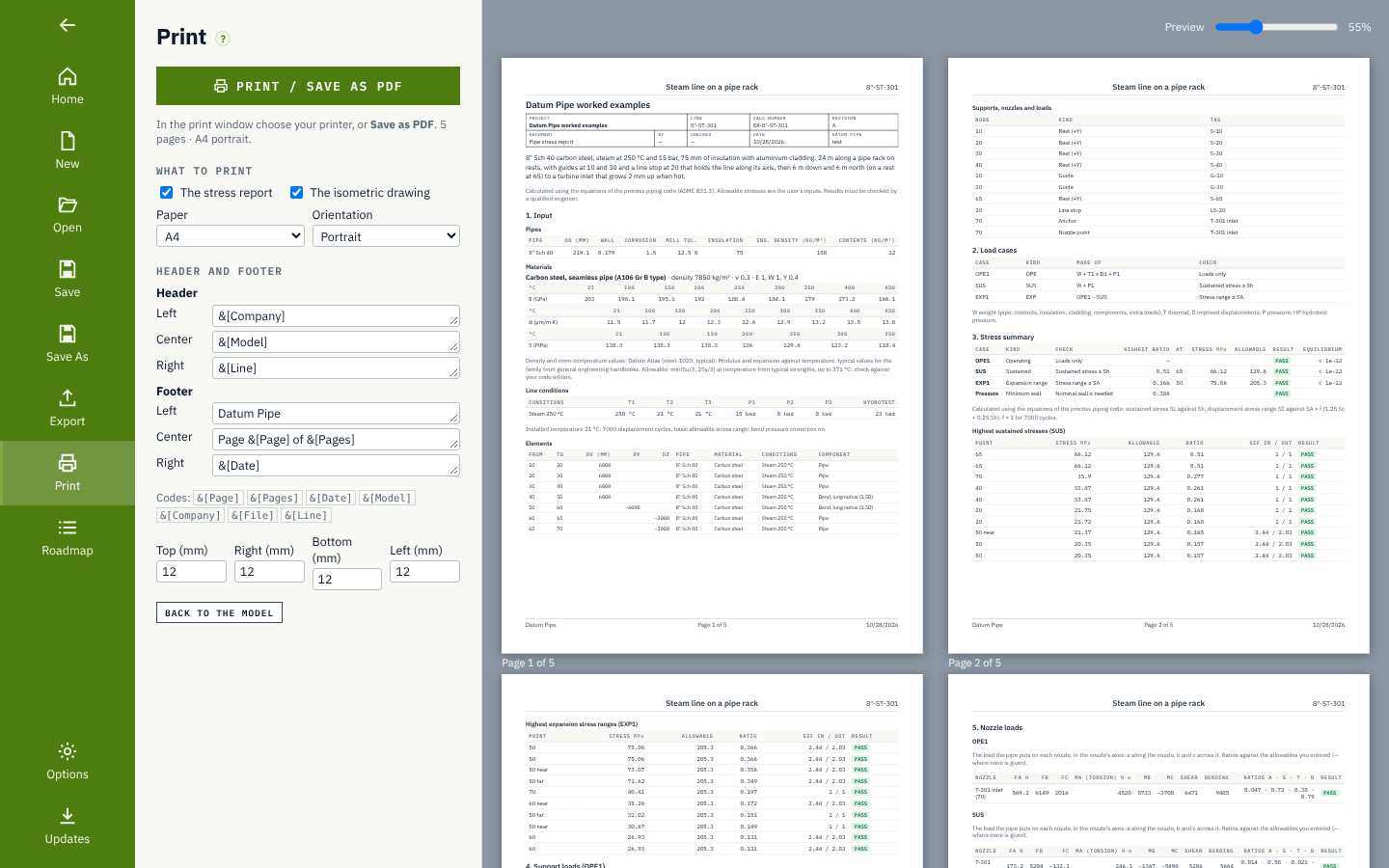
Roadmap
- Donev0.1.5
Code check fixes
- Minimum wall: the t < D/6 limit and the bend thickness factor
- Reducers checked at both ends
- Tee stress factors with the effective branch section modulus
- Pressure elongation of straight pipe
- Two supports holding one direction: each reports its own share of the reaction
- Donev0.1.7
One-way rests and gaps
- Rests that lift off (iterative solve until every support's state settles)
- Gaps on guides and line stops
- Results show which supports lifted off or closed
- Benchmarks for lift-off and a closing gap
- Donev0.1.8
Friction
- Friction at rests and guides
- Equilibrium check including friction forces
- A friction benchmark
- Nextv0.1.9
Wind and seismic
- Wind loads (pressure on the projected area)
- Static seismic loads (g-factors)
- Occasional load cases and the occasional stress check
- Plannedv0.1.10
Spring hangers
- Spring hanger selection from hot load, travel and load variation
- Spring data entered by you (rate, range), with typical values
- Plannedv0.1.11
Import and benchmarks
- Import of plain-text piping component files from design tools
- The public piping benchmark problems published by nuclear regulators in Help › Verification
- Milestonev0.2.0
Nonlinear supports and more loads, complete
- Everything in 0.1.5–0.1.11 reviewed, with the verification record and examples updated
- No new features: 0.2.0 marks the stage as finished
- Laterv0.3
Equipment and flanges
- Nozzle checks to the published pump, compressor and steam turbine standards
- Flange leakage check
- Local stresses at vessel nozzles
- Relief valve thrust
- Broken into small 0.x.y steps before it starts
- Laterv0.4
Dynamics
- Natural frequencies and mode shapes
- Harmonic response
- Response spectrum
- Broken into small 0.x.y steps before it starts
- Laterv0.5
More codes
- Power piping and European piping code equations
- Buried pipe
- Cold spring
- Broken into small 0.x.y steps before it starts
- Goalv1.0
Validated
- A validation report covering every analysis type
- A user guide
- A signed installer
- Broken into small 0.x.y steps before it starts
Releases
v0.1.8Friction at rests and guides.
Friction. Rests, guides, line stops and restraints can have a friction coefficient μ (0.3 is typical for steel on steel, 0.1 for PTFE slide plates). It acts across the support's direction: a rest resists the pipe sliding horizontally, a guide resists it moving along the pipe.
Sticking and sliding. In each load case a support with friction holds the pipe while the force that needs is within μ × the load pressing the support; beyond that the pipe slides, and the support pushes back with exactly μ × its load against the movement, in whatever direction the pipe moves across it. A rest that lifts off has no friction. This is solved in the same iteration as one-way rests and gaps; sliding forces are found exactly from the support's own flexibility, one support after another, so supports at one node settle together.
Results. Support Loads shows each support with friction as sticking or sliding, with its friction force, which is part of the support's load and of the equilibrium check.
Examples. The steam line's rests and guides have μ = 0.3.
Verification. A new benchmark: friction at a heated rest, sliding (μ P, and the movement ε L − μ P L / EA) and sticking (E A ε) (38 checks).
v0.1.7One-way rests and gaps.
One-way rests. A rest can let the pipe lift off: it pushes the pipe up but never pulls it down. New rests are one-way; the Inspector switches it. Rests in files from earlier versions stay two-way, so their results do not change.
Gaps. Rests, guides, line stops and restraints can have a gap: below the pipe for a rest, on each side for the others. The support takes no load until the pipe has moved across it.
How it is solved. With one-way rests or gaps, each load case is solved again until every such support has settled as touching or open: a touching support must push the pipe, not pull it, and an open one must not be passed. The expansion range is still the difference of the operating and sustained results. If only open gaps hold the piping in some direction, they keep a light stiffness (1 N/mm) so the case can be solved, with a warning.
Results. Support Loads shows each one-way or gapped support as touching, open or lifted off, with the pipe's movement and the gap, and how many solves the case took.
Examples. The examples' rests are one-way, and the steam line's guides have 3 mm gaps.
Verification. Two new benchmarks: a one-way rest under a cantilever (lifting off when pushed up, carrying the load when pushed down) and a gap closing at a cantilever's tip (34 checks).
v0.1.6Windows now lists the publisher as Datum.
v0.1.5Code check fixes, and where every equation comes from.
Minimum wall.
- A bend is also checked at its intrados, where the wall needs most metal: the design thickness uses the bend factor I = (4R/D − 1)/(4R/D − 2).
- A pressure design thickness of D/6 or more now fails, with a warning: the thin-wall equation does not apply there.
- A reducer is checked at both ends, each with its own pipe (diameter, wall, corrosion and mill tolerance); it was checked at its large end only.
Tees. The branch of a tee uses the effective section modulus Ze = π r₂² Ts, with Ts the lesser of the run's wall and ii × the branch's wall. Analysis Settings can turn it off for code editions that use the branch pipe's own section modulus.
Pressure elongation. Straight pipe can grow with its pressure in the operating cases (ε = (σL − ν σh)/E). Off unless you choose it in Analysis Settings; the sustained case never includes it.
Shared supports. Two rigid supports holding the same direction at one node now share its load equally, with a warning; the first one took it all.
Sources. Help › Sources lists every equation with where it is published in the open engineering literature: Barlow and Lamé, the membrane theory of a torus, von Kármán, Clark and Reissner, Markl, Rodabaugh and George, and beam theory. The README, NOTICE and report say that Datum Pipe contains none of the code's text, tables or figures and is not affiliated with or endorsed by ASME.
Verification. Three new benchmarks: a bend's wall at its intrados, pressure elongation between two anchors, and a tee branch's effective section modulus (29 checks).
v0.1.4Polish: the build to start with. Every example analyzes, draws its isometric and prints its report.
Fixes from an independent review of the engine.
- An expansion range between two operating cases now takes the hot allowable Sh at the hotter of the two cases; it took the second case's even when the first was hotter, which was on the unsafe side.
- Guides and line stops at a tee act along the run; the branch was averaged into the pipe's direction, so a line stop could take loads across the pipe. At a corner, where there is no single direction, Datum Pipe now says so.
- A tee drawn as the end of its branch takes its stress intensification from the run pipe, and a tee without a straight run gets its plane from its legs (with a warning).
- Bends' stress intensification factors use the lowest operating pressure for the pressure correction (on the safe side in every case); their flexibility still uses the highest.
- A flexible anchor's stiffness applies to its three movements; its rotations are held.
- A reducer's small end uses its own pipe's corrosion allowance in the sustained stress.
Isometric. The sheet fills the window at the proportions of a landscape page, with its title block the same width.
Report. The title block's labels print in their boxes (they were pushed to the foot of the first page).
Results. Code stresses are listed in table order, element by element, with each bend after its straight part; Worst first still sorts them by ratio.
Examples. The turbine nozzle of the steam line points the right way (from the turbine into the pipe).
Checked. A final pass over every worked example: each one analyzes with its reactions balancing its loads, draws its isometric and prints a report of four to six pages. New screenshots for the README and the family site.
Get Datum Pipe.
Free and open source (MIT). Installs in seconds for your user account, with no administrator rights, and updates itself from inside the app.